A series-parallel circuit is a combination of series and parallel circuits, where some components are connected in series and some are connected in parallel. This means that there are multiple paths for the current to flow through the circuit, and the total resistance, voltage, and current are not the same for all components. To analyze a series-parallel circuit, we need to apply the rules of series and parallel circuits to different parts of the circuit, and use complex numbers to represent the impedance, voltage, and current of each component.
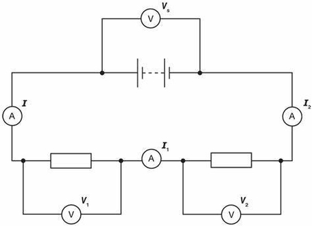
Here is an example of a series-parallel circuit with three resistors and two capacitors:

The impedance (Z) of a component is the ratio of the voltage (V) across it to the current (I) through it, and it depends on the frequency (f) of the AC source. The impedance of a resistor (R) is equal to its resistance, and it does not change with frequency. The impedance of a capacitor (C) is inversely proportional to the frequency and the capacitance, and it has a negative phase angle of 90 degrees. The impedance of an inductor (L) is directly proportional to the frequency and the inductance, and it has a positive phase angle of 90 degrees. The impedance of a component can be written in polar form as Z = |Z| ? ?, where |Z| is the magnitude and ? is the phase angle.
To find the impedance of each component in the circuit, we need to use the following formulas:
– Z_R = R
– Z_C = 1 / (2?fC) ? -90°
– Z_L = 2?fL ? 90°
We can also use the following table to organize the values of impedance, voltage, and current for each component:
| Component | Impedance (Z) | Voltage (V) | Current (I) |
|———–|—————|————-|————-|
| R_1 | | | |
| R_2 | | | |
| R_3 | |